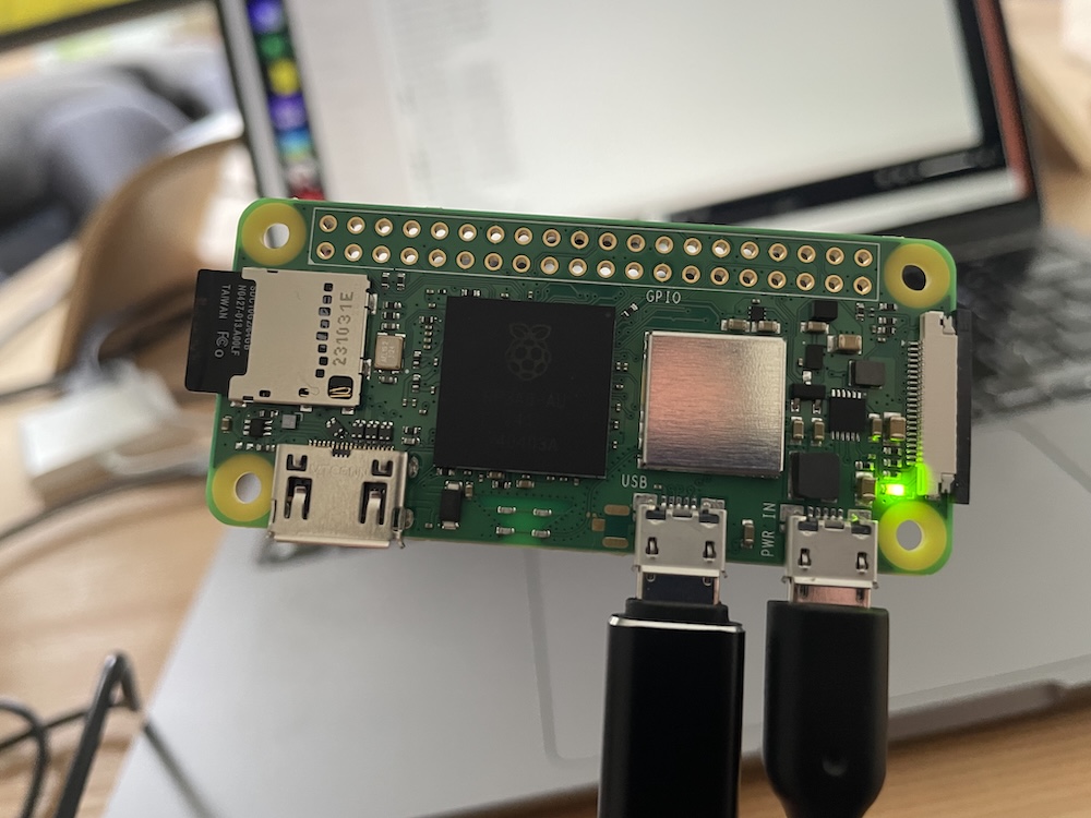
After some rummaging around on the web followed by a gruelling struggle to get the Raspberry Pi Zero to allow code editing and execution over USB I finally managed to set up the Pi to act as my MoCap system’s hub. The Pi Zero is a full-blown computer and not set up like a microcontroller to simply power on and execute a set code. Thankfully it is possible to modify the settings of the Pi Zero to achieve a similar microcontroller-like functionality, through the combination of loading a headless operating system (in this case, Raspberry Pi OS Lite) and disabling a series of background tasks. I still need to do this second part more thoroughly, but I have an minimal viable setup capable of running dedicated code on boot.
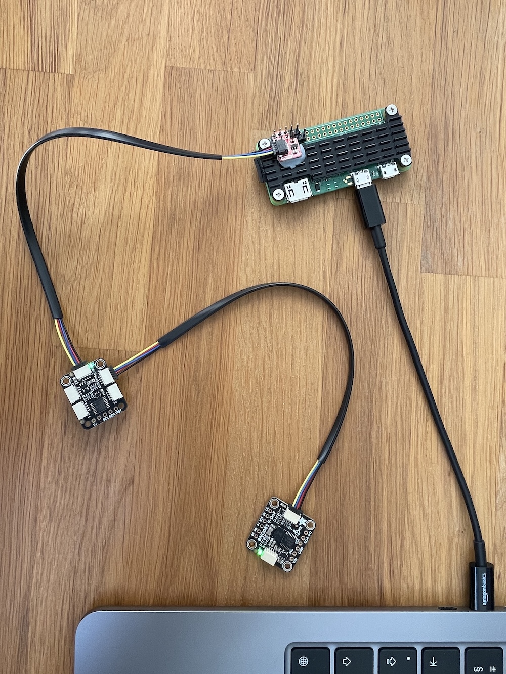
Next up was the task of communicating with a motion sensor via a multiplexer, which is needed in order to eventually bus data from the many sensors into the Pi for broadcasting. This proved quite tricky, but with a little help from some example code fed into my virtual assistants ChatGPT and DeepSeek, I was able to detect the multiplexer, the motion sensor, and then assign an intuitive name, in this case RightArm. This will be built out for the entire suit with a similar naming convention for each sensor.
Each motion sensor can have one of two addresses, meaning two sensors can occupy the same i2C communication channel using the same wires. I2C stands for inter-integrated circuit, and is the protocol we’ll be using to connect the sensors to the Pi Zero. Each 4 channel multiplexer can handle up to 8 sensors. My main suit needs to read from 16 sensors, which means 2 multiplexers, each with 8 sensors connected. Great stuff.
In discussions with ChatGPT around methods to make the system as efficient, and therefor fast as possible, we came to the conclusion that two 4 channel multiplexers was better than one 8 channel, as it allows for more sensor reads between channel switches, which saves a few milliseconds. It doesn’t sound like much, but at 200 reads per second, the delays add up fast. Using this same thinking, we also decided to leverage the second i2C bus that is present in the Raspberry Pi Zero, which dedicated to a camera connector by default, but can be tweaked to read sensors instead. This means we can now have one multiplexer per i2C channel, allowing for two data feeds at once, reducing the traffic on each bus and speeding up the transfer of data.
The next hurdle was cable length. I2C is designed to work over very short distances, however we need it to span the length of a tall adult human to be on the safe side. Most motion capture suits come in small, medium, and large sizes to cater for a variety of sizes, but they use the same wiring, so we build a suit for the largest size and that caters for all eventualities – aside from maybe basketball players, but that’s a problem for another day. To address the cable length issue we’ll need to ensure there is suitably strong signal strength down the cables, meaning we’ll likely need some resistors to help boost voltage to ensure signal integrity. Thankfully both the multiplexers and motion sensors are equipped with resistors, so we can tweak the resistance as needed. (The multiplexers have resistors that you can physically disable depending on requirements, so we can swap these out in our circuit to suit our needs).
The upper body wiring will be a little shorter than the lower body due to the fact that we will not be supporting the hands in the main suit setup, these will be handled by separate Raspberry PI PICO microcontrollers, meaning we’ll essentially have three motion capture rigs in total, 1 big one and 2 smaller ones, all working in unison… hopefully. To test out signal integrity I repurposed a nice long ethernet cable to extend the prototype to 2 metres. This worked well with a single bus channel, however when adding a sensor on a second channel the voltage started to drop slightly, so pull-up resistor will be needed to keep the voltage up. The multiplexers I was using for the test do not have these resistors built in, but thankfully the proposed ones for the second prototype do, so we should be good to go.

Once the connections were made it was a simple case of establishing a websocket connection from the Pi Zero to my MacBook over WiFi. I say simple because I was able to repurpose existing code from my previous motion tracking proof of concept. After the tweaking of some settings, I was comfortably and reliably transmitting data at around 200 frames per second, so the concept is a solid one, we just need to preserve as much speed as possible as we scale up the system.
It’s worth pointing out that this is all a little overkill for our prototype, but it is essential preparation to ensure the system can scale up to handle the amount of data we wish to process. So far, so good. Let’s just hope the theory works in practice!
Next up, building the PiCapture suit hub.