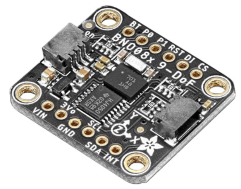
In order to develop the hardware for the motion capture system, I’ll need to purchase more specialised sensors needed to capture the motion data. There’s no other way around this, these sensors are tailored for this kind of use case and there are no viable alternatives. The sensors needed for a motion capture project such as this are 9 degrees of freedom inertial measurement units, or 9-DOF IMUs for short. We’ll just call them motion sensors to preserve our sanity. This is some pretty complex data fusion from several different sensors, all combined to create a single measurement that we can use to map each sensor’s position and motion within physical space.
To combine the various motion and orientation readings from each motion sensor requires valuable processing resources which is our first problem. Normally this kind of number crunching would either be reserved for the host computer running the motion capture software or possibly processed on the control unit located on the performer’s body connected to all the motion sensors. But, w’re looking to run this whole setup using compact Raspberry Pi devices, so we really need to offload any data fusion somewhere else, and reduce the size of the data we need to transmit wirelessly to the host computer.
Thankfully we can! We’ll be taking advantage of some relatively recent developments in sensor data fusion which utilise dedicated processors housed on each IMU. These little dedicated processing chips do one job, combining all the sensor readings into a single set of quaternion measurements – and they do it very fast too! Thanks to these amazing chips, we can distribute a significant amount of processing across each sensor, easing the load on the Raspberry Pis, allowing them to focus solely on reliably receiving and transmitting the motion data from all the sensors over to the host computer via WiFi – and doing so 200 times per second (hopefully). That’s a lot a work to do, and these fusion sensors are what will hopefully make this high resolution motion capture suit possible.
Now that we have our motion sensor brains, we need a heart for the suit. This comes in the form of a Raspberry Pi Zero 2W. This delightfully small computer will form the hub of the suit from which all the cables will flow to the various sensors across the body. To further optimise the data transmission we’ll need to batch process the incoming sensor data, combining it with a timestamp, so that we can sync the motion on our destination motion capture app. The initial setup will not cater for hand tracking, this will be handled by two additional Raspberry Pi PICO microcontrollers, complete with their own WiFi modules, allowing us to further distribute data capture and transmission. So, we will end up with three individual Raspberry Pi devices sending three sets of data to the motion capture app. This load balancing is needed to ensure we can keep our frame rate as high as possible. We’re very optimistically aiming for 200 measurements per second, but realistically we need to achieve 60 per second reliably for some nice high resolution motion capture. Finger’s crossed.
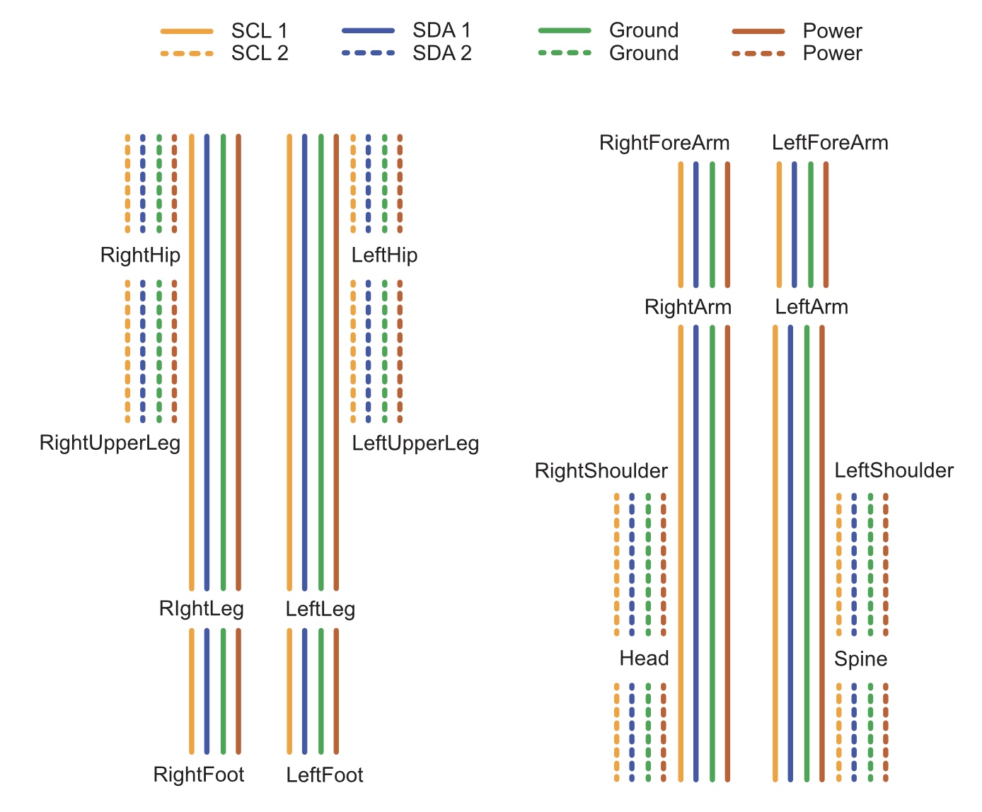

The next step is to build our prototype and see how these theoretical numbers play out. I’ve already spent some time with my virtual assistant ChatGPT working through a variety of designs to help achieve the throughput and wiring to get the most performant setup possibly. We’re looking at a system utilising the i2c communication protocol, across two multiplexers to enable the most efficient channel switching possible to reduce delays between sensors readings. Instead of one 8 channel multiplexer switching eight times with 2 sensors per channels, we’ll use two 4 channel multiplexers , meaning we can read two channels at the same and switch channels four times per multiplexer. This is slightly more complex, but quicker, and we need speed!
On top of this we need four cables coming from the Raspberry Pi to connect the sensors, which will mean eight wires per cable to cover all the connections. This wire needs to be thin, flexible, and require good shielding to maintain excellent signal integrity – we can’t have lots of noise on the wire as it will screw up our data. I decided on RJ456 network cable due to its twisted pair composition to help prevent cross talk and found a slimline version online that provided thinner, more flexible cable whilst maintaining suitable shielding. Looking good so far, now it’s time to put this all to the test with our prototype setup.